 Repair Procedure
Installing the KN-8828B-2K+ Upgrade Kit Repair Procedure
Installing the KN-8828B-2K+ Upgrade KitClick on the small images on this page to see a higher-resolution version of the image. The larger image will open in a new window that can be closed after viewing
|
|
| NOTE: These procedures are designed to assist you in the installation of a Hottop KN-8828B-2K+ upgrade kit. Please be aware that this is an advanced procedure which requires the near-complete disassembly of the roaster. Please read through all these procedures before beginning and verify that you have the tools, ability, and experience to complete the tasks as outlined here. There have been variations in some components over the years. Your machine may vary slightly from the images seen here.
Some Tips
- Take photos as you go to assist in things like where wires are routed
- Use various containers to hold removed parts and their hardware to eliminate the need to wonder what screw goes in which spot. Note that over the years there have been numerous variations on the types of screws and where they go. We urge you to carefully store and mark the screws so that they can be installed into their original locations.
- Take notes as to the order you do things since, for the most part, this will have to be reversed when you assembly the machine
- Use care when removing wires. Insulation can be damaged by metal parts
- The "K" thermocouples have solid-core wiring that is brittle. Do not flex the wiring more than necessary, and be particularly careful at the end that connects to the control panel.
For more helpful hints like these, see our "User Repair Tips" article. This artiucle will be most helpful for those not experienced in these sorts of procedures.
|
Navigation Tip: All thumbnails link to larger images of the same photo. |
| 1 |
|
NOTE: If you are not removing the roast chamber (a necessary task to install UK-106 or UK-108) skip to step 4.
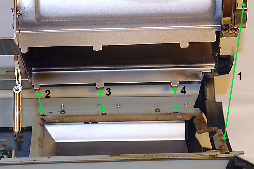
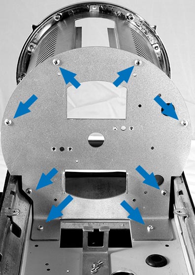
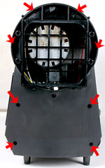
After removing all components as directed at the beginning of this procedure the frame should look something like this. If you plan on removing the roast chamber for cleaning or you are changing the horizontal frame member (such as when upgrading to "-2" function), remove the two screws indicated here (previously removed).
|
|
| 2 |
|
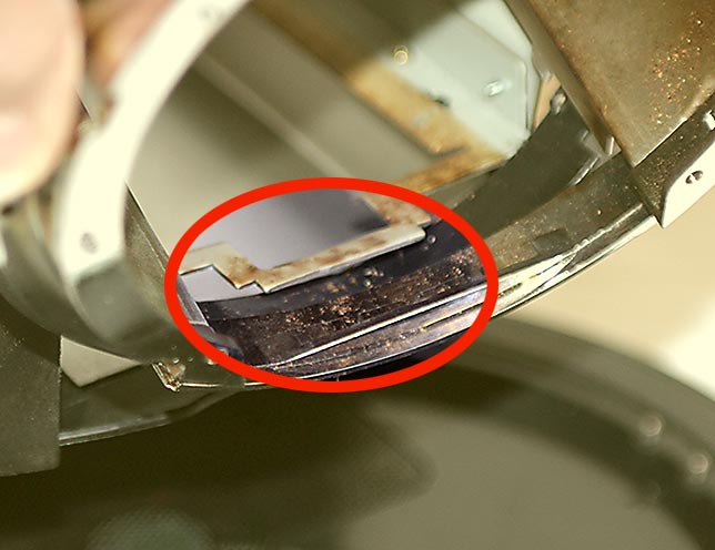
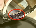
Before removing the roast chamber assembly from the machine, take note of how the lower edge of the bezel is located UNDER the tab on the front edge of the frame.
Work the above-mentioned assembly upwards and slide it forward so that the lower edge of the bezel clears the frame as indicated here. |
|
| 3 |
|
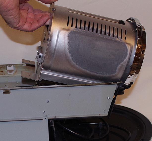
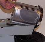
You can now lift the rear end of the chamber assembly up. This assembly is made up of three parts: the inner roast chamber wall, the roast chamber rear wall, and the bezel to which the bearing plate normally is attached.
|
|
| 4 |
|
Remove the 8 screws that hold the roast chamber rear wall in place and separate the rear wall from the roaster.
If you have removed the roast chamber from the roaster use care as the roast chamber outer wall may be under some tension and may "spring open" to some extent. |
|
|
OPTIONAL:
Now that the roaster is mostly in parts it is a good time to consider giving it a thorough cleaning. We have a video center with repair videos HERE. You will find a number of disassembly videos there which will be helpful. One in particular is called Cleaning a Dirty Hottop Roaster which has a number of useful tips on giving the roaster a thorough cleaning. We also have a detailed article entitled User Maintenance of Hottop Coffee Roasters. |
If you ARE NOT installing UK-106 or UK-108, reinstall the roast chamber assembly (if necessary), then go to step 11. |
|
|
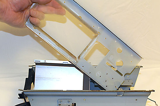
If you ARE installing either the UK-106 or UK-108 upgrade kits and need to replace the horizontal frame member, (example of that part seen here), continue with step 5.
|
|
|
| 5 |
|
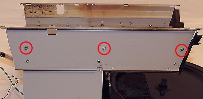
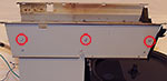
On the left side of the machine remove the three screws indicated here.
|
|
| 6 |
|
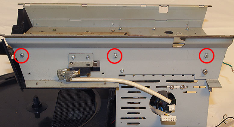
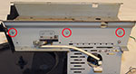
On the right side of the machine remove the three screws indicated here.
|
|
| 7 |
|
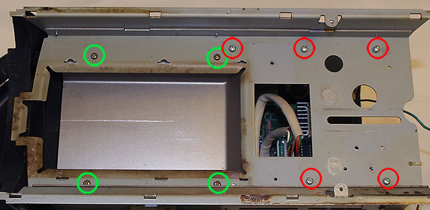
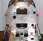
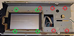
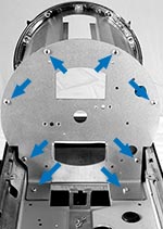
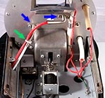
Looking at the top of the horizontal frame member that will be replaced, remove the nine screws shown here. Be aware that the screws marked with the green circles hold the chaff tray chamber into which the chaff tray slides. These DO need to be removed.
|
|
| 8 |
|
The old horizontal frame cross-member can now be lifted out of the machine. |
|
| 9 |
|
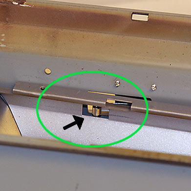
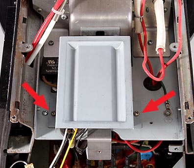
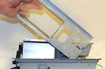
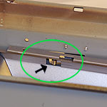
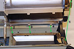
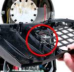
Before installing the new frame member, locate the chaff tray chamber so that the chaff tray safety switch is located in the rectangular open of the tray as seen here.
It is now time to install the new frame member (not shown). Use the images from the previous three steps to be sure that all screws are replaced. Start by loosely installing the four screws marked in green in step 7. Now loosely install the remainder of the screws from steps 5 through 7. When all screws are in place, tighten them.
|
|
| 10 |
|
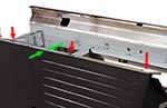
Install the roast chamber assembly:
The front edge of the bezel has to first slide under the front edge of the frame
(refer to the image in step 2). To accomplish this, tip the rear end of the assembly up so that the assembly is at an angle.
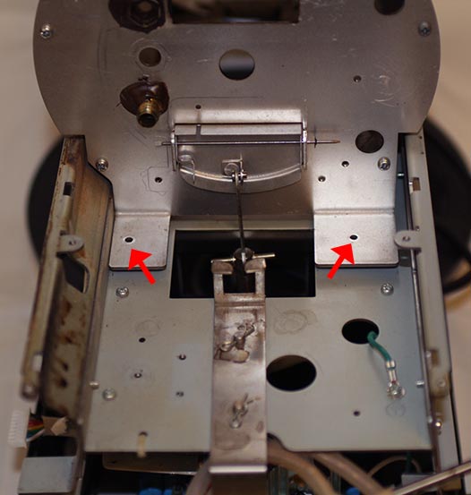
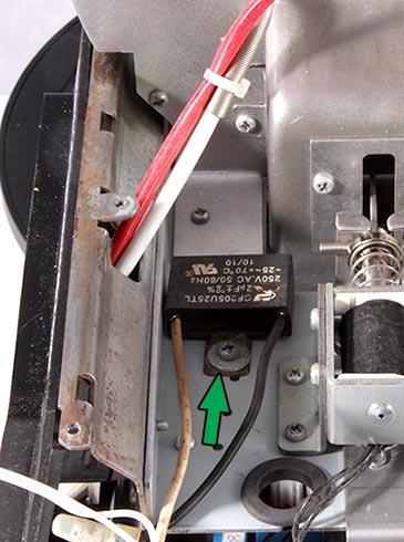
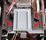
NOTE: There are three tabs along each side of the inner chamber's edges. These fit into slots in the frame as indicated by the green arrows. It is important to make sure that all six tabs drop into their respective slots before proceeding. |
|
| 11 |
OPTIONAL: Step 11 AND 12 are optional. While it is possible to continue without completing them, it is highly recommended that you complete steps 11 and 12!
There have been numerous variations over the years with the frames of the different models of Hottop coffee roasters. This situation is one of those. The black plastic side panel is held in place along the top edge by four tabs, and along the bottom with protrusions that interlock with the base. Of the two screws that hold the "+" panel in place, the mounting hole in the new KN-8828B-2K+ which is behind the control panel is in a different location than earlier models. Because of that the screw cannot be used without the following modification.
We highly recommend completing this modification because if you need to remove the control panel in the future, the side panel
may be under enough stress that when pulling the control panel off it can break the mounting tabs of the panel.
If you choose to not do this modification, skip to step 13. |
|
|
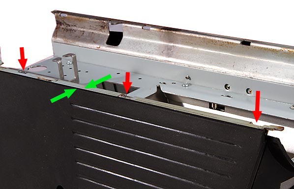
Temporarily place the KN-8828B-2K+ side panel on the control panel side
of the machine. Make sure that the four tabs along the top edge are in the frame's slots and that the top edge (indicated by the green arrows) is aligned with the top edge of the frame.[NOTE - the left side poanel is shown here, but both panels mount in the same way for this step]. Insert the screw that is closest to the front of the roaster. This properly locates the side panel for the next step.
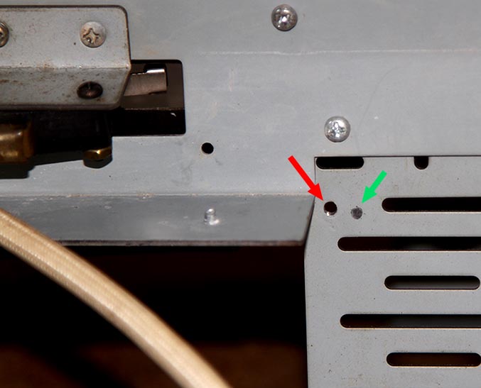
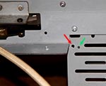
Inside the void where the control panel will eventually mount there is a small hole is on the upper left area. That is where the second screw which holds the side panel in place will go. There is likely no hole there. Use a fine tip marker or pencil, and using the side panel as a template, mark the metal frame through that empty screw hole. If in doubt, examine the original side panel to get an approximate idea where that hole is located. Now remove the screw and remove side panel.
|
|
| 12 |
|
If you see the mark you just made in the previous step and it is in a different location from that of the original hole, you will need to drill a hole for the screw's new location. Use a drill bit that fits through the original hole with a bit of room to spare. The bit should slide through the hole fairly easily but not be too loose (if in doubt, you can always make the hole larger, not smaller). Center punch the hole, cover the main board with a cloth, and using a slow speed, drill all the way through the side panel. Remove the cloth and blow out any metal shavings from the area of the main board. TIP: Grease the grooves of the drill bit. The grease will hold nearly all the metal shavings as the bit goes through.
Start the screw that was originally used there and when you verify that it is perpendicular to the surface, run it in with a good-fitting screwdriver. If it gets difficult to turn, back it out a little and continue until it gets about half way through its length (mid-threads), then remove it and continue with the next step..
|
|
| 13 |
|
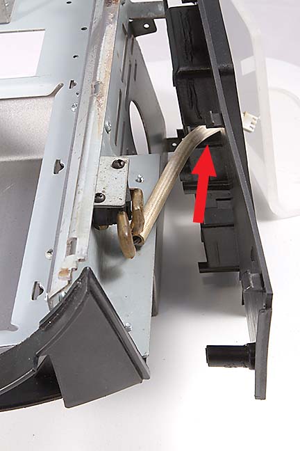
If your machine is equipped with the chaff tray switch (see here), first feed the switch's cable through the indicated hole in the "KN-8828B-2K+" right side panel. Replace the right side panel and secure it with both screws.
|
|
| 14 |
|
Install the new KN-8828B-2K+ roast chamber rear wall. Six screws hold it to the roast chamber outer wall and two screws secure it to the horizontal frame member. |
|
| 15 |
|
Install the ejection door and the bean ejection chute and its cover. |
|
| 16 |
|
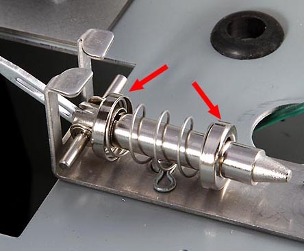
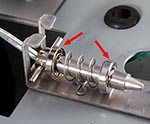
If installing the new style eject solenoid return spring, note the location and orientation of the spring seats. |
|
| 17 |
|
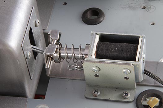
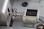
Install the solenoid coil.
|
|
| 18 |
|
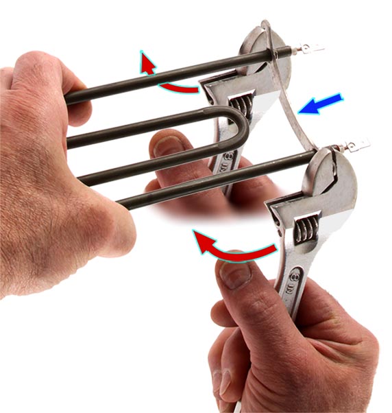
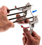
Clean the heating element's heating surface with alcohol.
Before installing the heating element, using a suitable wrench or pair of pliers, bend the mounting tabs of the element in the direction shown, one at a time (two pliers are shown here for effect only to illustrate the direstion to bed the tabs). Note the direction they are being bent (the red arrows) relative to the orientation of the element as indicated by the blue arrow. Only bend these about two or three degrees - just a slight amount. The goal is to have the element close to the outer roast chamber wall when the element is installed. Why? You do not want the element touching the roasting drum, nor do you want it touching the outer wall. It is easy to move the element away from the wall when the drum is removed because of the large range of motion afforded in the roast chamber. It is is virtually impossible to move the element closer to the wall because there is limited range of motion in that direction.
|
|
| 19 |
|
Install the heating element. After the two screws are tightened, look inside the roast chamber. A properly located heating element should be close to, but not touching the roast chamber's outer wall. Adjust as necessary. If it is too close to the outer wall, bend it out by hand. If too far from the wall, the element will have to be removed and the mounting bracket will have to be bent as described in the previous step.
Install the fusible link. Route the wires through the grommeted hole.
NOTE: The kit includes two long red wires which have male spade terminals at their ends. Early models with the old style fusible link which connects to T3 and T4 on the main circuit board. Use these two red wires to replace the heating element wires which connect from the heating element to terminals T5 and T6 on the main circuit board.
Later models with the black fuse connected to T3 and T4 can use one of the wires to connect one heating element terminal to the Main Circuit Board, thus replacing one of the old wires.
|
|
| 20 |
|
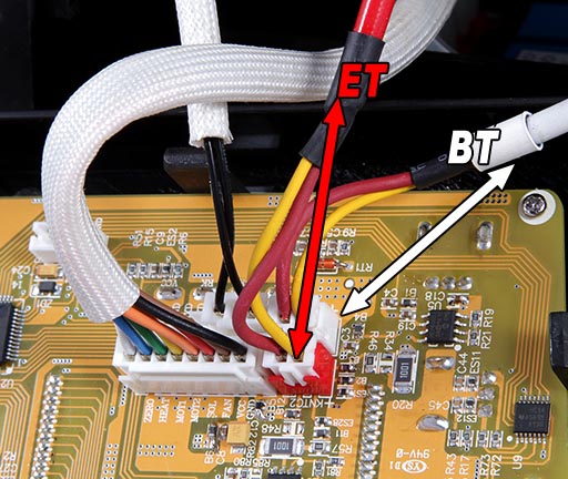
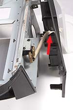
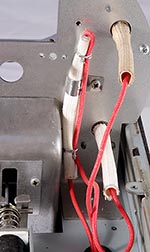
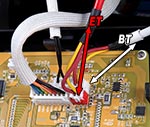
Install the two new thermocouples from this side of the roast chamber's rear wall. First route the leads through the hole in the frame towards the control panel's future location and then place each of the sensors' ends through their respective mounting holes.
Note the position of the red and white thermocouples. The red thermocouple must be the Environmental Temperature (ET) sensor. Use a tie wrap in the location as seen here, but tighten it just enough to hold it in place and do not cut it at this time. It may need to be adjusted after the drum motor is installed.
Also route the green ground wire from the power cord through the same hole and secure it as seen here. |
|
| 21 |
|
Install the Main Motor's capacitor before installing the motor itself! |
|
| 22 |
|
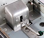
Now install the drip guard over the solenoid if so equipped.
If the machine was not originally equipped with the Solenoid Drip Guard, refer to the special instructions HERE. We recommend installing the drip guard as it has the potential of greatly extending the life of the solenoid. |
|
| 23 |

|
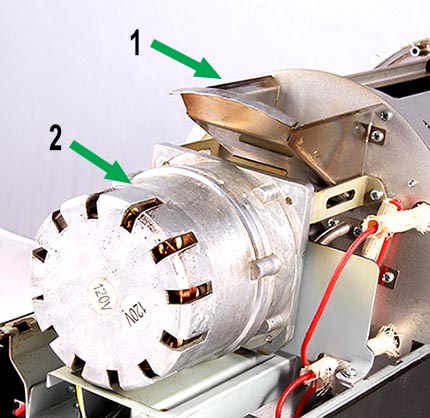
Install the bean loading chute (1)
Install the rubber seal on the motor's shaft and install the drum motor (2). Be careful not to pinch any of the heating element wires. When installing the motor note that all four screws should have lock washers.
First loosly install the top two screws, then install the third screw in the frame on the same side as the control panel (the right side of the roaster). When those three screws are in place, tighten them.
Now take note of the alignment of the mounting bracket of the last screw. If it does not align properly with the threaded hole in the frame you will need to bend that mounting arm for proper alignment. A small pliers (or even two) can be used. Get it as close as possible so that when inserting the screws only the smallest force to keep the alignment is needed to start the screw. DO NOT STRIP THE THREADS IN THE FRAME! |
|
| 24 |
|
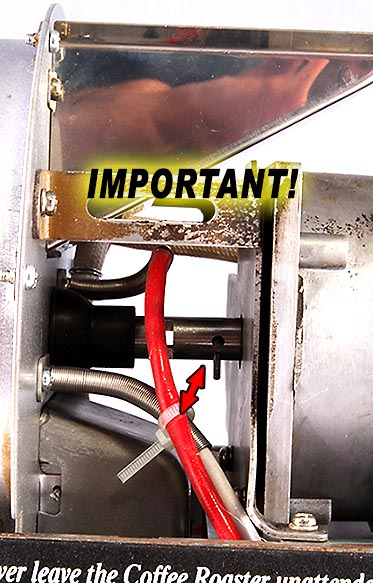
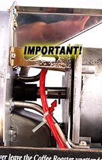
IMPORTANT!
After
installing the drum motor, carefully examine the routing of the thermocouple leads in relation to the motor's drive coupling and its clevis pin. It is critical that the driven parts do not damage the thermocouple leads when the roaster is in operation. Be sure that they will stay properly located. |
|
| 25 |
|
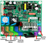
WIRING
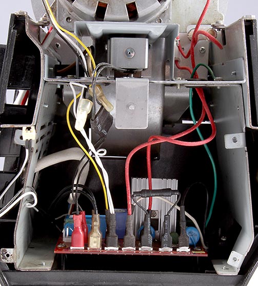
This image shows the routing of all the wires (see below for connection points).
At this point the data cable should also be connected to the main board and run through the frame so that it can be connected to the control panel.
|
| |
|
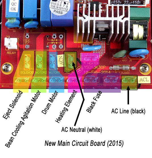
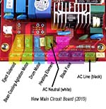
For clarity, this image identifies all the wiring locations on the new main circuit board (note the red color of the board material). They differ from the earlier boards in that the AC supply connections are in a different location. In particular, note the location of the AC neutral connection.
NOTE:
"Motor 1" on the circuit board is the drum motor.
"Motor 2" on the circuit board is the bean cooling agitation arm motor
|
| |
|
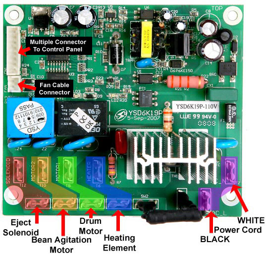
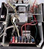
For your reference, here is the original main circuit board with its connection points identified. |
|
| 26 |
|
Here are the connections for the new "KN-8828B-2K+" control panel. Note the color coding on the sockets which correspond to the color coding of the thermocouples. The red, ET thermocouple must plug into the red socket. The other two cables are the chaff tray switch and the data cable. Not all sockets on the control panel will be occupied. These are the only cables that connect to the rear of the control panel.
WARNING: NEVER pull on the thermocouple wires to unplug the thermocouples from the control panel. The wires can be easily damaged. Only grip the connector plug itself with a suitable pair of pliers or other similar tool that can grip the connector plug securely! |
|
| 27 |
|
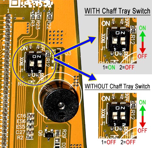
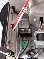
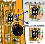
If your machine DOES NOT HAVE THE CHAFF TRAY SWITCH (that is, in the last step, if you only had three cables), find this dip switch on the back of the control panel and move switch 1 to off (switch 2 is off by default).
WITH CHAFF TRAY SWITCH: 1=ON 2=OFF
WITHOUT CHAFF TRAY SWITCH: 1=OFF 2=OFF
With all cables installed on the back of the control panel and the dip switch properly set, move the control panel into place and press firmly to snap it into the side panel. Press along the outer edges of the front of the panel. Do not press on the display area and do not press on the switches.
|
|
| 28 |
|
Before replacing the rear cover first be sure to verify that all wires are correctly installed and that all wires are secured as they were when you began.
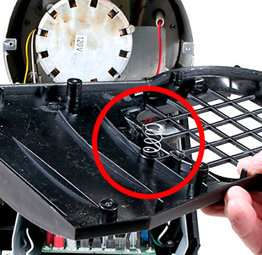
Now install the emergency eject mechanism's return spring in the cover. Next, feed the main fan's cable through the hole below the grill.
|
|
| 29 |
|
With the spring in it's well inside the back cover and the fan's connector through the rear cover, install the cover on the back of the machine, being careful that no wires are pinched in the process.
Starting with the two bottom screws, loosely install those, then working in pairs, going up the cover, continue installing pairs of screws until all screws have been inserted and started into their threaded holes. Once the cover is properly in place, tighten all screws. DO NOT OVER TIGHTEN!
|
|
| 30 |
|
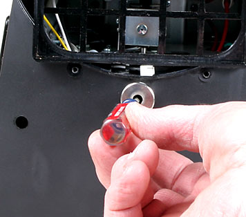
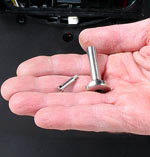
The Knob is held in place by the special screw seen here
|
| |

|
With the screw fully in the knob with its threads protruding, hold the screw in place by inserting the screwdriver into the knob, and then insert the knob through the cover. Tighten the screw firmly. Pull and release the knob a few times to be sure the emergency eject mechanism moves smoothly and freely, and look inside the roast chamber to be sure the eject door is opening and closing when doing so. |
|
| 31 |
To complete the procedure, reverse the remainder of the disassembly order carefully:
- Main fan
- Drum
- Bearing plate
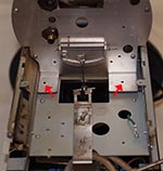
After the drum and bearing plate are installed, check carefully that the heating element does not touch the drum.
Use a wooden tool to gently rotate the drum and listen for rubbing sounds
- Front cover
- Main filter
- Bean loading chute cover
- Cooling tray
- Heat guard grills
|
|
32 |
|
WARNING!: Before attempting to roast coffee, turn roaster on as if to start a roast, and then IMMEDIATELY hit the EJECT button
DO NOT ADD COFFEE BEANS FOR THIS TEST!
Use a flashlight to look inside the roasting chamber and be sure that the Ejection Door opened fully. Do not roast coffee until you are sure that the Ejection Door opens properly.
Failure to do so may result in a fire hazard!
| |
|
| 33 |
Finally, be sure to run a full roast without beans before roasting coffee. The heating element and other parts need to be "broken in" and residue from the production process needs to be burned off. Do so out of doors to avoid getting the odor in your structure.
|
|