 Repair Procedure
Fusible Link Replacement/Update
Repair Procedure
Fusible Link Replacement/Update
Click on the small images on this page to see a higher-resolution version of the image. The larger image will open in a new window that can be closed after viewing |
|
| 1 |
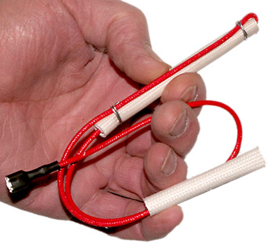
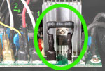
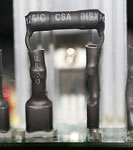
The machine is protected from overheating by a length of special wire. In the rare occurrence that the safety features of the machine fail and the roasting chamber overheats, the Fusible Link melts. It cannot be repaired and must be replaced.
Begin by following these procedures:
Front Cover
Bearing Plate and Drum
Remove Fan
Remove Rear Cover
Remove Top Cover
|
| 2a |
|
Examine the Main Board terminals T3 and T4. If you DO find that resistor jumper between terminals T3 and T4 you already have the current Fusible Link update installed. In that case:
To replace the Heating Element CLICK HERE
To replace the Fusible Link only CLICK HERE.
If you DO NOT have that resistor jumper installed, examine Step2b below:
|
|
| 2b |
|
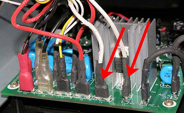
Examine the main Board terminals T3 and T4. If there are two wires as shown here then you have the older style fusible link and you are on the correct page to replace the Fusible Link Update (Your main board may look different from the image shown here, but terminal numbers will be the same). Continue with Step 3 below.
NOTE: Over time there has been some variation on the colors of some of the wires. The wires you will be dealing with may be red or may be white. So long as you chose the correct wires as identified by their connection points the color of the wires does not matter.
|
|
| 3 |
|
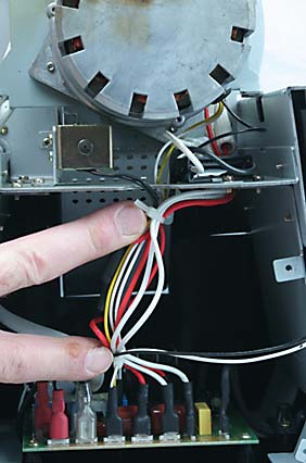
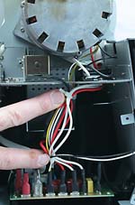
Cut the two tie wraps holding the wire bundle above the Main Circuit Board together. Discard the clippings (Do not leave them in the machine).
|
|
| 4 |
|
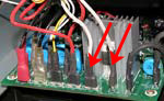
Use a needle nose pliers to remove the two wires shown here which connect the Fusible Link to the Main Circuit Board. Your board may look different from that shown here, but the terminal numbers on the Main Board are T3 and T4.
|
|
| 5 |

|
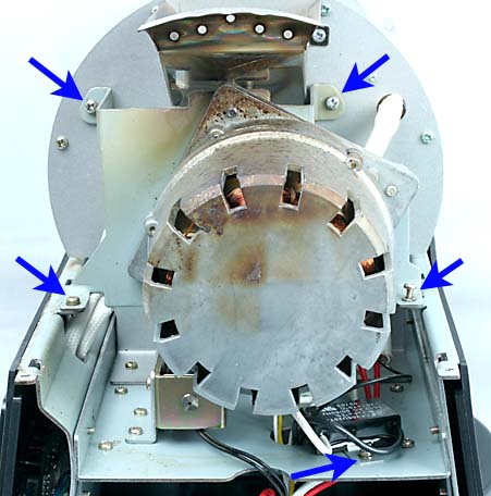
Follow the directions to Remove the Motor. It is NOT necessary to completely remove the motor. Just the 4 screws holding the motor's mounting bracket to the machine. No wires need to be removed. Looking at the rear of the machine, move the motor off to the left to revel the fusible link. Do not allow the motor to hang by its wires. If you cannot safely support the motor, either get assistance or remove it completely. Take care to not scrape or damage the insulation of the wires.
|
|
| 6 |
|
Remove the screw holding the Fusible Link's bracket to the roasting chamber's rear wall. Remove the fusible link from the machine.
|
|
| 7 |
|
Remove the top wire connected to the heating element. Trace the wire down through the Dividing Plate to the Main Board below, and remove its other end which is attached to either terminal T5 or T6 depending on which wire you chose. Remove the wire from the roaster. It will no longer be needed.
|
|
| 8 |

|
To replace the Fusible Link, attach the bracket that was included with the repair kit to the new Fusible Link. Do not reuse the old bracket!
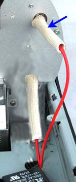
IMPORTANT: Note that the bracket attaches to the center, cylindrical, firm portion of the Fusible Link. Squeeze the link as shown here to find that portion of the link.
WARNING: If you fail to place the Fusible Link under the bracket in the correct location, it could result in damage to the Fusible Link and/or a fire hazard. The thick, hard portion of the link approximately at its midpoint. That is what the bracket must press against.
|
|
| 9 |
|
Loosely attach the new Fusible Link to the roaster using the same hole. Use the new screw included with the kit. Be sure that the center portion of the fusible link, located under the bracket, sits flat against the back wall of the roasting chamber, and that no wires are trapped under the new link. Be sure to locate the Fusible Link and its wiring so that they cannot contact the heating element.
|
|
| 10 |
|
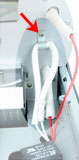
Move the top end of the new Fusible link so that it is clear of the mounting hole for the Main Motor bracket. The wires in the link can be bent, but take care not to bend them close to the bracket, near the fusible portion itself (the stiff portion). When the link is clear of the hole as shown here, tighten the screw. Once again, make sure that the link is firmly up against the metal plate to which it is mounted.
WARNING!: The fusible link is part of the safety system designed into the Hottop coffee roasters. Its operation depends on sensing the heat of the roaster. It must be in firm contact with the metal of the roasting chamber as descried above. Failure to assure that this is done correctly can create a fire hazard!
|
|
| 11 |
|
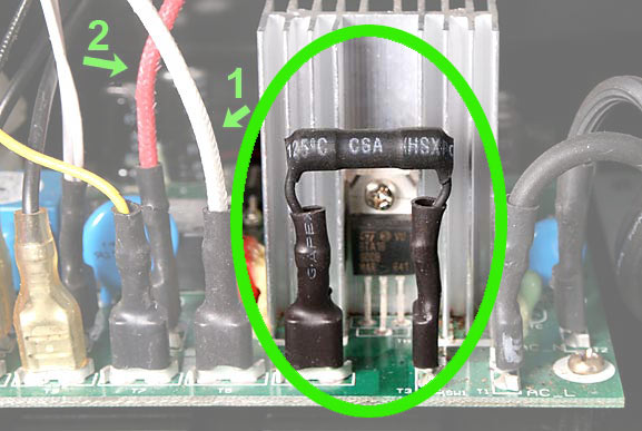
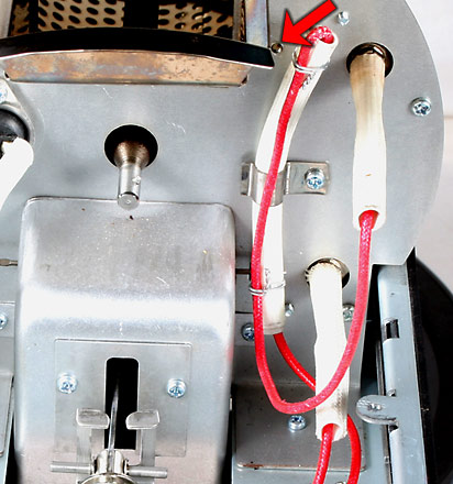
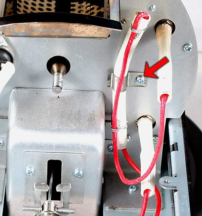
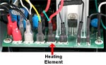
The Fusible Link has two wire leads. The short lead with the woven insulating cover attaches to the heating element. One wire coming from the Main Board is already attached to one connector of the heating element. The short Fusible Link wire with the woven sleeve insulation attaches to the other heating element connector. It does not matter which of the two heating element terminals you use for the Fusible link. The arrow here indicates that in this particular installation the Fusible Link is being attached to the upper Heating Element terminal.
IMPORTANT: Be sure to check that both spade connections on the heating element are tight. If loose, remove and use a small pair of pliers to carefully squeeze the female spade clips closed a bit and check for proper fit again. Use caution when pushing on the heating element's attachment points.
|
|
| 12 |
|
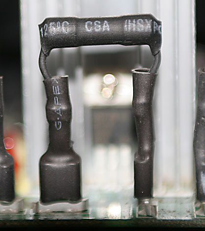
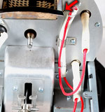
Terminals T3 and T4 are vacant at this time from the removal of the original Fusible link. The jumper resistor that was included with the update kit is attached to these two terminals as shown here. The use of a pair of small needle nose pliers is recommended. Grasp only the spade connectors under the black insulation. DO NOT push on the resistor nor its leads directly as they may be damaged.
|
|
| 13 |
|
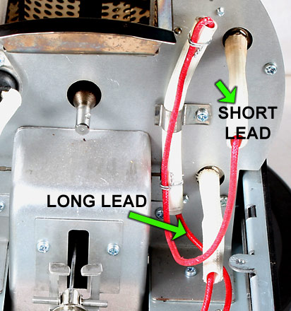
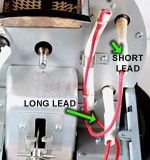
Connect the Fusible Link to the Main Board. The two wires indicated here are:
1 - The lead from the Fusible Link
This is the longer lead from the new Fusible Link. Feed it through one of the holes in the metal dividing plate down to the Main Board. Take care to not scrape or damage the insulation of the wires.
2 - The lead from the Heating Element.
These two wires connect to terminals T5 and T6. It does not matter which lead is on which terminal, so long as these two leads connect, one each, to these two terminals.
|
|
To complete the procedure:
Replace the Motor
Replace the tie wrap(s) on the wires leading to the main board
Replace Top Cover
Replace Rear Cover
Replace the Main Fan
Replace the Drum and the Bearing Plate
Replace Front Cover |