 Repair Procedure
Eject Mechanism & Solenoid Repair Procedure
Eject Mechanism & Solenoid
Click on the small images on this page to see a higher-resolution version of the image. The larger image will open in a new window that can be closed after viewing
|
|
| 1 |
NOTE: This procedure is for the KN-8828B-2 and KN-8828P-2 ONLY. For earlier models use THIS page.
Begin by following these procedures:
Fan
Rear Cover
Bearing Plate and Drum
Top Panel
Motor |
|
| 2 |
|
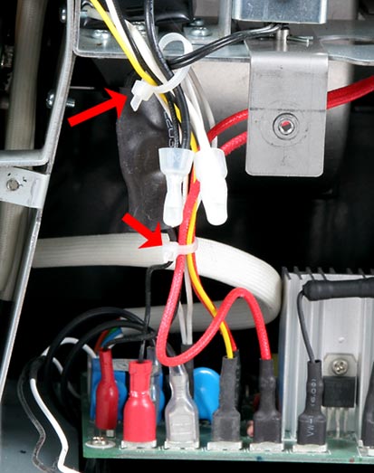
Clip the tie wraps that hold the wire harness together.
|
|
| 3 |
|
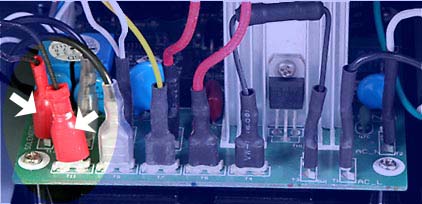
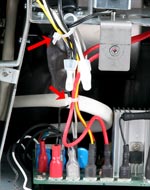
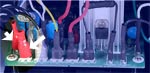
Remove the two wires from the Main Board that power the solenoid. Before removing, note the routing of the wires from the Solenoid to the Main Board. Use needle nose pliers and grip only the thin area of the red connector. Do not pull on the wires. THrough this entire process, take care to not scrape or damage the insulation of the wires.
|
|
| 4 |
|
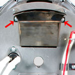
Remove the bean Loading Chute by removing its two retaining screws.
|
|
| 5 |
|
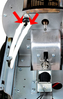
Slide the insulation back a little and remove the two wires connected to the Thermal Sensor. Move the wires off to the side.
|
|
| 6 |

|
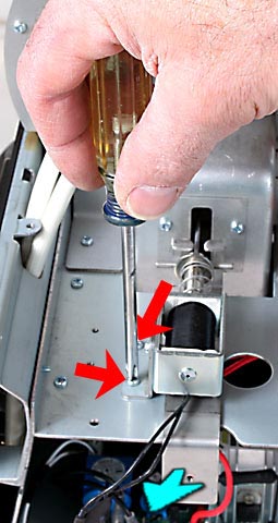
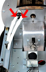
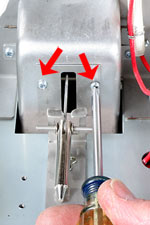
Remove the two Phillips head screws indicated here and slide the Solenoid towards the rear of the machine to remove it. The actuating shaft will remain attached to the Ejection Door.
|
|
| 7 |
|
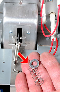
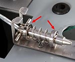
After removing the Solenoid, slip the spring and then the washer off of the Solenoid Plunger.
If only replacing the solenoid, installation is the reverse order of the above procedure. Skip to STEP 18.
|
|
| 8 |

|
Remove the two screws holding the Ejection Chute Cover Plate on the Ejection Chute and remove the cover.
|
|
| 9 |
|
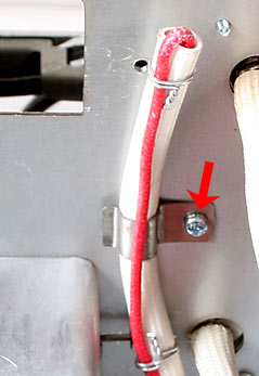
If you are continuing on and will be removing the Bean Ejection door, it can be helpful to remove the Fusible Link at this time. Before removing, use a marker or pen to create a small mark on the insulation above and below the clamp's location indicate the location of the clamp on the link before removing the screw.
|
|
| 10 |
|
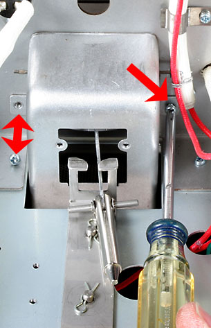
Remove the two screws holding the Ejection Chute and slide the chute upwards to remove it from the machine.
|
|
| 11 |
|
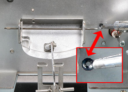
Use a suitable pair of pliers and remove the small retaining spring washer from the Hinge Wire. It will help to remove the heating element wires at this time if they are in your way. It may also help to have someone else hold the other end of the wire with a second pair of pliers while you work the retaining washer off. Pull the Hinge Wire out from the opposite side and remove the Ejection Door.
WARNING: Be sure to retrieve all dropped parts from inside the machine.
|
|
| 12 |
|
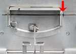
Reinstall by reversing the above steps. Begin assembly by holding the replacement door in position and sliding the new hinge pin into place, and reinstalling the Retaining Spring Washer. Leave some free play for the hinge pin.
|
|
| 13 |
|
Slide the Ejection Chute back into place being sure that the Solenoid's Plunger is through the opening and replace the two screws holding the Ejection Chute.
|
|
| 14 |

|
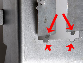
Place the Ejection Chute Cover Plate on the Ejection Chute. Note that the bend of two tabs on the small plate must point away from you and slide into the two slots in the Chute.
|
|
| 15 |
|
Replace the two screws that hold the Ejection Chute Cover in place.
|
|
| 16 |
|
Replace the Fusible Link at this time.
CAUTION: The clamp must be seated in the same location as it was before removal. Be sure the clamp is over the "thick" part of the link which is the fusible portion of the device.
|
|
| 17 |
|
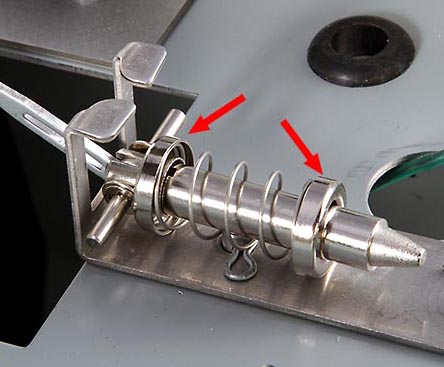
All replacement "-2" solenoids now come with cupped washers that replace the old style flat washer. Slide the cup washer with the flat side facing away from the spring onto the Solenoid's Actuating Shaft, then slide the spring into place, and finally the second cup washer, again with the flat side facing away from the spring. The ends of the spring should be nestled into each of the washers' cavities.
|
|
| 18 |
|
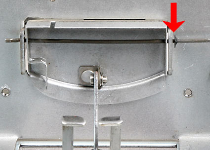
Slide the Ejection Solenoid's coil back into position and fasten to the base with two screws as seen here. Be sure that the wires are located safely and not pinched.
IMPORTANT: Once the solenoid coil is correctly attached, manually operate the emergency eject lever by pulling (as indicated by the blue arrow) and then releasing it a few times. The ejection chute door should open and close smoothly.
|
|
| 19 |
|
Replace the Bean Loading Chute
|
|
| 20 |
|
Replace the two wires connected to the Thermal Sensor. Be sure that the connectors make a firm connection on the spade terminals of the Thermal Sensor. If necessary, use a pair of pliers to close the female spade connectors slightly to assure a firm connection.
|
|
| 21 |
|
Replace the wires for the Solenoid on the Main Board at connection points T11 and T12
|
|
To complete the procedure:
Replace the Motor
Replace the Top Panel
Replace the Rear Cover
Replace the Fan
Replace the Bearing Plate and Drum |
|
WARNING!: Before roasting coffee, turn roaster on as if to start a roast, and then IMMEDIATELY hit the EJECT button
DO NOT ADD COFFEE BEANS FOR THIS TEST!
Failure to do so may result in a fire hazard!
|
|