 Repair Procedure
Upgrade Kits
Repair Procedure
Upgrade Kits
Click on the small images on this page to see a higher-resolution version of the image. The larger image will open in a new window that can be closed after viewing
|
|
| NOTE: These procedures are designed to assist in the installation of a Hottop Upgrade Kit (UK-100, UK-101, UK-102, UK-103, or UK-104). Please be aware that this is an advanced procedure which requires the near-complete disassembly of the roaster. Please read through all these procedures before beginning and verify that you have the tools, ability, and experience to compete the tasks as outlined here. There have been variations in some components over the years. Your machine may vary slightly from the images seen here.
Some Tips
- Take photos as you go to assist in things like where wires are routed
- Use various containers to hold removed parts and their hardware to eliminate the need to wonder what screw goes in which spot.
- Take notes as to the order you do things since this will have to be reversed when you assembly the machine
- Use care when removing wires. Insulation can be damaged by metal parts
- The "K" thermocouples have solid-core wiring that is brittle. Do not flex the wiring more than necessary, and be very careful at the end that connects to the control panel.
In addition to other documents referred to below,
please use the following PDF instructions which cover upgrading:
FROM KN-8828 and KN-8828D models:
Upgrade to: KN-8828P-2 or KN-8828P-2K
Upgrade to: KN-8828B-2 or KN-8828B-2K
Specifically, pay attention to step #19a and #19b
Those steps cover important points necessary to allow later
control panels to operate with these two earlier models of machines.
|
|
For the Following Kits:
UK-100, UK-101, UK-102, UK-103, or UK-104
Begin by removing all loose parts (cooling tray, bean loading chute cover, rear filter). Then complete these procedures: |
And if your roaster is currently a:
KN-8828, KN-8828D, KN-8828B, or KN-8828P
Begin by removing the following:
Fan
Rear Cover
Bearing Plate and Drum
Top Cover
Drum Motor
Eject Solenoid
Heating Element
Fusible link
Control Panel
Temperature Sensor
For Kits UK-103 and UK-104 skip to step 4 below.
For kits UK-100, UK-101, UK-102 also remove
Side Panels
Then continue with Step 1 below:
|
If your roaster is currently a:
KN-8828B-2 or KN-8828P-2
Begin by removing the following
Fan
Rear Cover
Bearing Plate and Drum
Top Cover
Drum Motor
Eject Solenoid
Heating Element
Fusible link
Control Panel
Temperature Sensor
For Kits UK-103 and UK-104 skip to step 4 below.
For kits UK-100, UK-101, UK-102 also remove
Side Panels
Then continue with Step 1 below: |
|
|
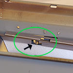
| 1 |
|
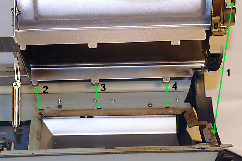
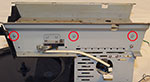
After removing all components as directed at the beginning of this procedure the frame should look something like this. Remove the two screws indicated here (previously removed).
|
|
| 2 |
|
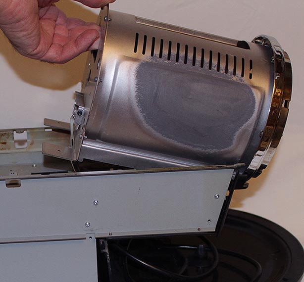
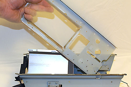
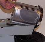
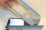
You can now lift the rear end of the chamber assembly up. This assembly is made up of three parts: the inner roast chamber wall, the roast chamber rear wall, and the bezel to which the bearing plate normally is attached.
|
|
| 3 |
|
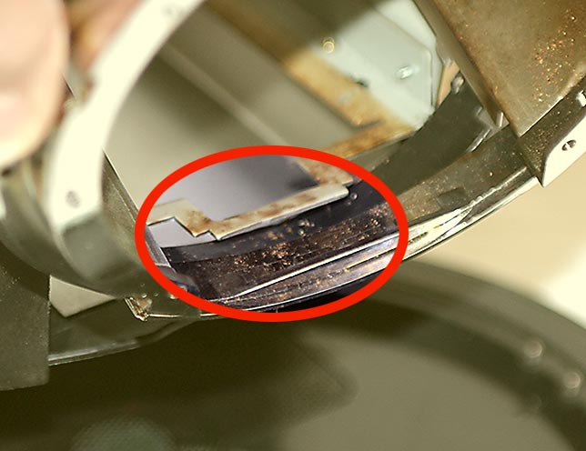
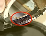
Before removing the roast chamber assembly from the machine, take note of how the lower edge of the bezel is located UNDER the tab on the front edge of the frame.
Work the above-mentioned assembly upwards and slide it forward so that the lower edge of the bezel clears the frame as indicated here. |
|
| 4 |
If you are installing upgrade kit UK-101, UK-102, UK-103, or UK-104
At this time remove the screws that hold the roast chamber rear wall in place and separate it from the roast chamber inner wall. Install the new rear wall for the K-thermocouple that came with the kit. Be sure that the 90 degree mounting tabs point in the same direction as the original wall.
Replace the rear wall retaining screws to secure the nrew rear wall to the roaster.
|
|
| |
OPTIONAL:
With the roaster completely assembled it it a very good time to give it a thorough cleaning. An inexpensive and effective cleaning agent is sodium percorbonate, an adduct of sodium carbonate and hydrogen peroxide. In water this turns to washing soda and hydrogen peroxide. Simply, it is sold as a cleaning agent and as a non-chlorine bleach. One of the most easily-found products containing this is Oxyclean (ALWAYS follow all instructions and safety procedures on the product's packaging. Use gloves and eye protection!). In a clean, plastic five-gallon bucket and add two scoops for heavily-soiled parts. Place the following parts in the bucket and then add enough water to cover the parts. A toothbrush can be used occasionally to help clean heavily soiled areas:
- Outer shell (remove top filter!)
- Chaff tray
- Bean loading chute
- Bean eject chute
- Bean loading chute cover
Clean the following parts with the cleaner you mixed in the bucket, but just use a brush and clean them without soaking. The finish on the inner chamber wall and the chrome on the bezel and front cover can be damaged from extended periods of soaking.
- Complete inner roast chamber assembly (removed in step 3 above)
- Front cover (remove gold screw) . not soak this part for any longer than it
NEVER use this cleaning method on ANY electrical parts or either of the filters. Plastic parts are safe in this cleaner based on our testing. Parts can safely soak overnight or longer if necessary. Heavily soiled parts may need to have the cleaning agent renewed for complete cleaning. Avoid scrubbing pads that can scratch plastic and polished metal areas.
NOTE- the only problem is that this will remove the heat warning paint on the stainless outer cover. Clean the outer surface of the shell with a cleaner suitable for stainless steel and place a wide strip of painters tape over the printed warning on the cover is recommended.
When the parts are clean, rinse them thoroughly in water and dry completely before continuing with the rest of this process! |
If you are NOT installing the "-2" update, and you have removed the roast chamber from the machine, go to step 10 and reinstall the roast chamber assembly and continue from there.
|
|
|
|
| 5 |
|
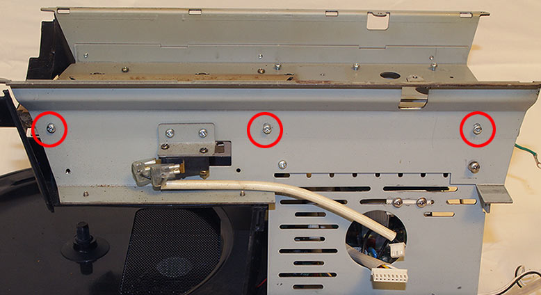
On the left side of the machine remove the three screw indicated here.
|
|
| 6 |
|
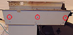
On the right side of the machine remove the three screws indicated here.
|
|
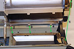
| 7 |
|
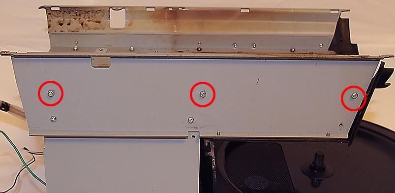
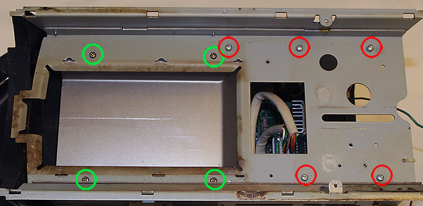
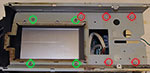
Looking at the top of the horizontal frame member that will be replaced, remove the nine screws shown here. Be aware that the screws marked with the green circles hold the chaff tray chamber into which the chaff tray slides. These DO need to be removed.
|
|
| 8 |
|
The old horizontal frame cross-member can now be lifted out of the machine.
|
|
| 9 |
|
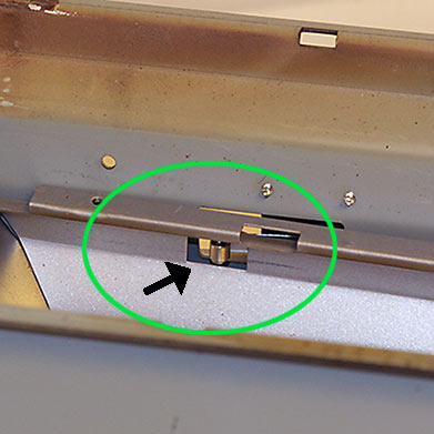
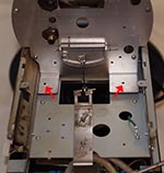
Before installing the new frame member, locate the chaff tray chamber so that the chaff tray safety switch is located in the rectangular open of the tray as seen here.
It is now time to install the new frame member (not shown). Use the images from the previous three steps to be sure that all screws are replaced. Start by loosely installing the four screws marked in green in step 7. Now loosely install the remainder of the screws from steps 5 through 7. When all screws are in place, tighten them.
|
|
| 10 |
|
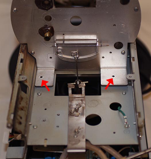
Install the roast chamber assembly:
1 - The front edge of the bezel has to first slide under the front edge of the frame (refer to the image in step 3). To accomplish this, tip the rear end of the assembly up so that the assembly is at an angle.
2 through 4 - Note that there are three tabs along each side of the inner chamber's edges. These fit into slots in the frame as indicated by the green arrows. It is important to make sure that all six tabs drop into their respective slots before proceeding. |
|
| 11 |
To complete the procedure, reverse the disassembly order carefully. Be sure to verify that all wires are correctly installed and that all wires are secured as they were when you began.
|
|
|
WARNING!: Before attempting to roast coffee, turn roaster on as if to start a roast, and then IMMEDIATELY hit the EJECT button
DO NOT ADD COFFEE BEANS FOR THIS TEST!
Use a flashlight to look inside the roasting chamber to be sure that the Ejection Door opened fully. Do not roast coffee until you are sure that the Ejection Door opens properly.
Failure to do so may result in a fire hazard!
|
|