Click on the small images on this page to see a higher-resolution version of the image. The larger image will open in a new window that can be closed after viewing
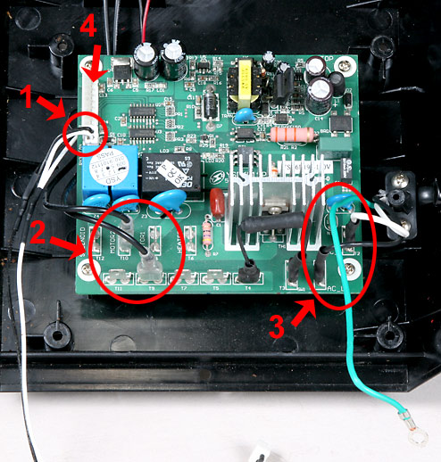
With the Base free of the machine, the main board is easily accessed. Begin by removing the remaining wires as indicated here:
1 - Fan Cable
2 - Agitation Motor wires
3 - White and Black Power Cord wires (note their positions)
4 - (Not shown) cable to Control panel
3
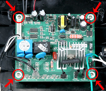
Next, remove the four screws indicated in this photo which secure the main board to the base.
4
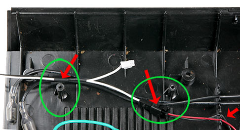
When replacing the Main board, be sure that the two sets of wires from the Agitation Motor and the Bean Cooling Fan are routed around the Main Board mounting studs as seen here.
Be sure that the edge of the Main Board with the male spade terminals faces to the rear of the base and replace the four screws. Attach the four wires removed in Step 1 above.