Click on the small images on this page to see a higher-resolution version of the image. The larger image will open in a new window that can be closed after viewing
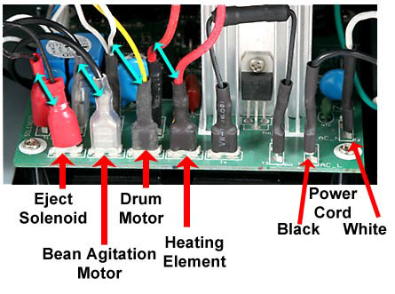
With the rear cover removed, disconnect the wires listed below. Take care to not scrape or damage the insulation of the wires.
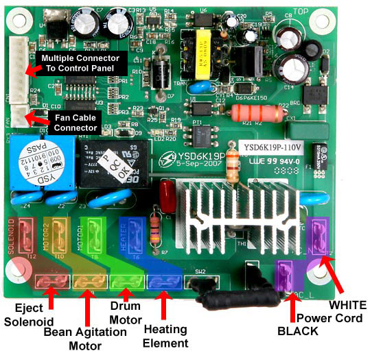
Refer to this photo for the location of the wires. If you choose, use a pen-style liquid paper applicator and mark the wires with a code you can remember (numbers or series of dots) and record this for proper replacement of the wires). The wires are in pairs:
Eject Solenoid
Drum Motor
Heating Element
Multiple Connector to Control Panel
3
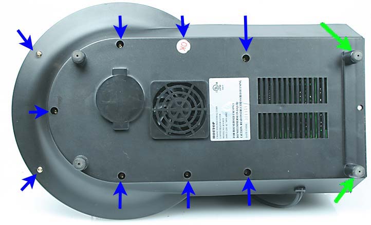
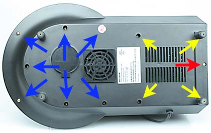
Next, remove the two rubber feet at the rear of the machine as indicated here by the green arrows. They are pressed into place and held by friction. Simply pull while "unscrewing" them and they will come out easily. Remove the 11 screws as indicated by all the arrows here. Note that there may be a sticker over one of the screw holes which needs to be removed to access the screw beneath it.
4
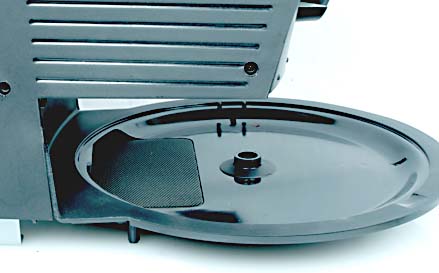
When all of these screw are removed the base can be separated from the machine. The bottom of the cooling tray stays in place on the machine and is not removed during this procedure.
5
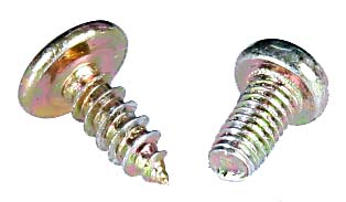
When reinstalling the base it is important to note that two different types of screws are used. On the left is a self-tapping screw. On the right is shown a machine screw.
6
The four machine screws go into the locations marked with the yellow arrows. The blue arrows indicate the locations of the seven self-tapping screws. The red arrow indicates an unused hole in the base. No screw goes there. Be sure side panels and cooling tray base are properly located and that no wires are pinched between the base and the rest of the roaster before tightening the screws.
7
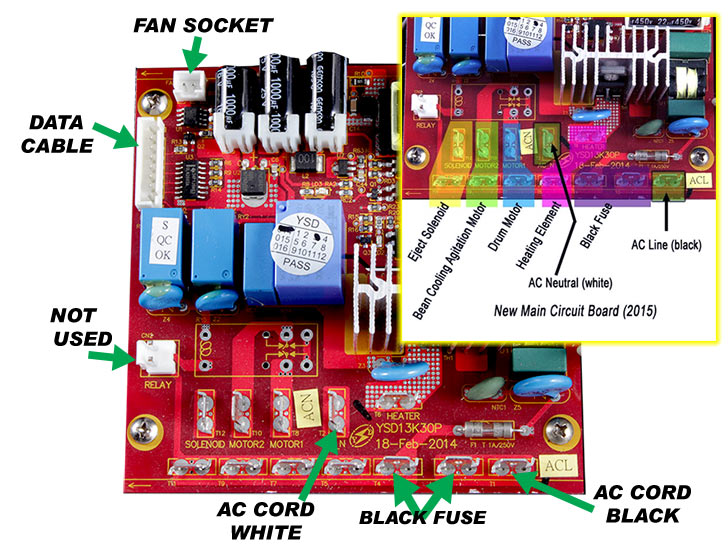
Replace the wires removed in step 1. Refer to this diagram for proper placement. These wires are not polarized. As long as each pair of wires goes back onto their proper pair of terminals it is fine. The only pair that have an orientation are the power cord wires. Be sure all connectors fit tightly on their terminals. Use a pair of pliers to gently squeeze them where necessary.
If you had the older green circuit board and are now installing the newer red-colored circuit board you will find that the placement of the connections differs from the previous design (green board). For clarity, this image will help you identify all the wiring locations on the new main circuit board. Check carefully as a number of the connection points have changed. Note that the AC supply connections are in a different location and the heating element connection is different as well.
"Motor 1" on the circuit board is the drum motor.
"Motor 2" on the circuit board is the bean cooling agitation arm motor
8
REASSEMBLY
Replace the screws in the following steps, but do not fully tighten.
a - Replace the Base and verify that the various mounting tabs of the Side Panels are properly engaged with the Base and metal framework.
b - Replace the Rear Cover.
c - Verify that all panels have been properly aligned, then tighten the various screws while holding the parts in alignment.