| 1 |
|
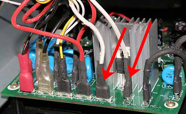
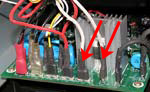
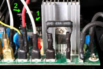
Your board may look different from that shown here, but the two wires of the Fusible Link are easily identified as they are covered with a white, woven insulation. They connect to the two terminals marked "T3" and "T4" on the Main Board. If your roaster has these two wires as indicated by the red arrows in this photograph, proceed using the instructions below.
If you do not have wires connected as seen here, follow the instructions in the blue column to the right.
NOTE: Over time there has been some variation on the colors of some of the wires. The wires you will be dealing with may be red or may be white. So long as you chose the correct wires as identified by their connection points the color of the wires does not matter.
|
|
| 2 |
|
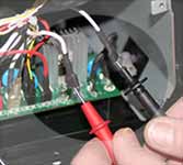
Use a needle nose pliers to remove the two wires shown here which connect the Fusible Link to the Main Circuit Board connected to the two terminals marked "T3" and "T4" on the Main Board.
|
|
| 3 |
|
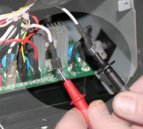
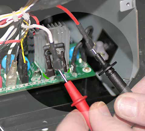
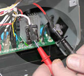
Using either an ohm meter or a continuity tester, test the fusible link by connecting the test device to the link- each of the two leads from the tester connected to each of the connectors of the fusible link as seen here.
Depending on the tester you are using, the results should show virtually no resistance (something in the neighborhood of a few ohms) or an open circuit (no continuity). Please refer to the instructions included with your testing device to assist in interpreting the results. If the results show that the fusible link is not conducting electricity (an open circuit) contact hottop@hottopamericas.com for fusible link replacement, or other repair procedures. Refer to the repair procedures for instructions on how to replace the fusible link.
|
|
| 1 |
|
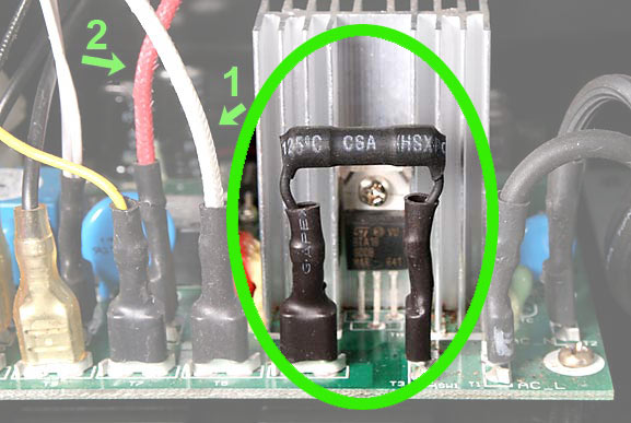
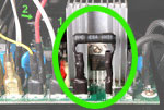
Your board may look different from that shown here, but check to see if your roaster has the black fuse connected to terminals T3 and T4 as indicated here by the green elipse. If your roaster has this fuse on the Main Board proceed using the instructions below.
If you do not have the black fuse seen here, follow the instructions in the yellow column to the left.
|
|
| 2 |
|
Use a needle nose pliers to remove the wire indicated by the numeral "1" here and the wire indicated by the numeral "2." Be aware that the positions of these wires may be reversed: the red wire indicated by the numeral "2" and the white wire may be in reversed positions. Note that your board may look somewhat different from that shown here, but terminal numbering is the same for all KN-8828X roasters. Disconnect these two wires.
NOTE: Over time there has been some variation on the colors of some of the wires. The wires you will be dealing with may be red or may be white. So long as you chose the correct wires as identified by their connection points, the color of the wires does not matter.
|
|
| 3 |
|
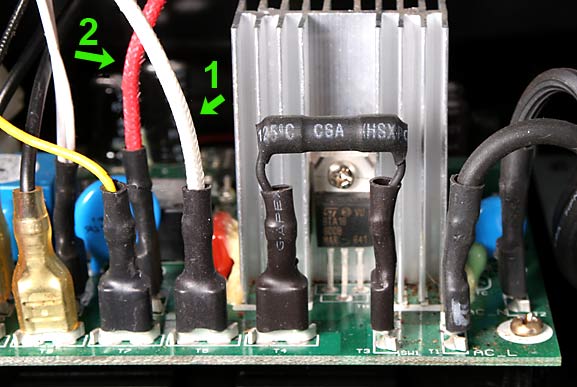
Using either an ohm meter or a continuity tester, test the heating circuit by connecting the test device to the two wires- each of the two leads from the tester connected to each of the connectors of the two wires as seen here.
Depending on the tester you are using, the results should show either very low resistance (something in the neighborhood of 20 ohms or so) or an open circuit (no continuity). Please refer to the instructions included with your testing device to assist in interpreting the results.
The test you just did tests both the Heating Element AND the Fusible Link. For further understanding of this, first refer to
Understanding the Heating Element Circuit.
Then use the instructions in Testing The Heating Circuit. Those two videos will guide you to a full diagnoses of the heating circuit.
|
|
When done, replace all connections on the Main Board, then replace the rear cover and main fan (and emergency eject knob if so equipped.
For further information on this, please feel free to e-mail Hottop Customer Service for fusible link replacement, or assistance with any other repair procedures. | |